PLC Programming Tools (Updated March 31, 2012)
A PLC is used to automate a process for reasons of speed, accuracy and repeatability. As much as possible, operator intervention in the process should be reduced or eliminated. Operators are slow, limited in the number of conditions that they can monitor simultaneously, easily distracted, not always present, mistake prone, easily damaged and with varying levels of motivation and skill. As much as possible, operator involvement with the process should be minimized.
Basic goals:
Use tools to automate PLC programming and help in maintaining the large amount of data used in even a small project.
Prevent bugs by creating easily maintained code with obvious program structure and clear program flow.
Simple error handling and display using low cost HMIs. PLCs are used in production; when the machine stops there should be at least a rudimentary error message showing why the machine is stopped to reduce downtime as much as possible. A program depends on certain set of input conditions to proceed at each step. If one of those conditions is not met, it should be clearly displayed as an error message for easier and quicker troubleshooting.
PLC Program Structure:
A PLC program consists of three program types: combinatorial and sequential code and a combination of sequential and combinatorial code. Combinatorial code is where the output depends only on current input conditions. There is no memory of previous events. An example is a lamp controlled by a toggle switch. If the switch is up, the lamp goes on. If the switch is down, the lamp goes off.
Sequential code has memory and the output depends on the previous state of the code or on a combination of previous events and current input conditions. A simple example is a lamp controlled by a single pushbutton. Pressing the button once will turn the lamp on. Pressing the button again will turn the lamp off. The state of the lamp depends not only on the button being pressed, but what state the lamp is in prior to the button press. If the lamp is on, a button press will turn it off. If the lamp is off, the same button press will turn the lamp on. The button press is transient and requires that the state of the lamp be memorized so that after the button is released the lamp will remain in its on or off state.
The state of the button also has to be memorized. The lamp state can only change if the button had previously been released prior to being pressed. If this information is not retained, a race condition will occur where the lamp state will continously alternate as long as the button is held down. Two bits of information have to be maintained; the state of the lamp and the previous state of the pushbutton.
Even this simple example requires the management of significant amount of data relative to the application. There is an output bit, an input bit, the current state of the lamp and the current state of the pushbutton, the sequence required to control the lamp and the combinatorial code required to interface between the sequence, the pushbutton and lamp.
Even worse, the number of states that a process can be in goes up exponentially with the number of bits. For example, a single lamp has two states; on and off. Two lamps have four states; both off, one on and one off, one off and the other off and both on. Three lamps have eight states, four lamps have sixteen states, five lamps have 32 states and so on with the number of states doubling with each additional lamp. If the lamps have to be turned on and off in a certain sequence, the complexity increases exponentially again as each state has to memorized. Adding additional inputs makes things even worse.
Controlling this explosion of complexity requires a disciplined approach in writing the program and managing the data associated with the program. The number of states can be contained by allowing the program to only be in a small number of states and preventing any possibility of it going into any of the forbidden states.
Going back to the simple pushbutton lamp control there is the following data and states:
Input: Pushbutton
Output: Lamp
States:
0) Lamp off, waiting for pushbutton to be pressed
1) Lamp on, waiting for pushbutton to be released
2) Lamp on, waiting for pushbutton to be pressed
3) Lamp off, waiting for pushbutton to be released
The output code is as
follows, note that the lamp output is only dependent on the current
state and not on an input or a combination of the current state and
input:
If in state 0, lamp is off
If in state 1, lamp is
on
If in state 2, lamp is on
If in state 3, lamp is
off
Transitions between states are dependent of both the
current state and the pushbutton input:
If in state 0 and the
pushbutton is pressed, go to state 1
If in state 1 and the
pushbutton is released, go to state 2
If in state 2 and the
pushbutton is pressed, go to state 3
If in state 3 and the
pushbutton is released, go to state 0
Although this code looks
correct, there is a very subtle bug. Depending on the memory
device used to retain the state, it is possible that the state of the
lamp at power up is not known. If a retentive type of memory is
used which retains its state when the power is off, the lamp will go
on at power up if it was on at power up or remain off if it was off
at power off, or even come up in a random state if memory gets
corrupted during the power on to off or off to on transition.
This may seem a little far fetched for such simple example, but think
of a machine which experiences a power failure in mid cycle. It
must be brought back to an initial known safe state prior to
operation to prevent possible damage. Ideally, the program will
do this automatically with minimal operator intervention.
Converting
the states above into a PLC program requires knowledge of how a PLC
operates.
The PLC continously runs a cycle at high speed where
it samples its inputs which can be either wires connected to the PLC
directly or through a network connection. It then sequentially
processes the program logic setting internal bits and memory
locations as directed by the program and then sets its outputs.
Although it may appear as if the program is run in parallel, the code
is run sequentially with only a single bit which is the result of
simple logic operation controlling the next program step. Even
the most complex ladder rung is broken down into simple steps with
each step either setting or resetting a single bit. This wil be
explored more later.
Since the program is cyclical, every
program step will be repeated over and over again. For simple
combinatorial logic this is not an issue. If a certain set of
input conditions causes a certain output, the output status should be
maintained as long as the input conditions are maintained.
Controlling the light with a toggle switch is a perfect example.
When the toggle switch is turned on, the PLC will read the switch,
process the logic which will set the output to turn on the lamp and
repeat this forever. When the toggle switch is turned off, the
PLC will read this, process the logic and turn off the output and
lamp a short time later and repeat this again until the toggle switch
is changed again.
When the pushbutton is used to control the
lamp, the cyclic nature of the PLC program is a problem. As the
PLC cycles, it reads the pushbutton input over and over again and
repeatedly applies the program logic and sets the lamp output
accordingly. If the lamp is off at the start of the cycle and
the pushbutton is pressed, after the logic is processed, the lamp
will be on at the end of the cycle. Since the lamp is now on
and the button is still pressed at the start of the next cycle, the
lamp will be turned off at the end of the cycle. On the next
cycle, since the lamp is off and the button is still pressed, the
lamp state will change again and so on until the button is released.
Even mid level PLCs have cycle times measured in thousandths of a
second which means even a very short button press can cause an
immense number of lamp output changes. The initial pushbutton
press has to be remembered from cycle to cycle to prevent the lamp
output state from changing every cycle as the button is held
down.
PLCs evolved as a direct replacement for a panel full of
relays with early PLC programs mimicking an electrical schematic.
A memory bit would consist of a self latching relay where one of the
relay contacts would be in parallel with with the normally open start
switch contacts and a second normally closed switch in series with
the coil. When the start switch is pressed, the coil is
activated and relay contact in parallel with the start switch keeps
the coil energized after the start switch is released. The
normally closed stop switch interrupts current to the relay when it
is pressed, resetting the circuit.
Although
this type of memory circuit is effective, the problem of exponential
growth occurs as multiple bits are used to memorize multiple states
in a program. If a simple approach is used where one bit is
used to to memorize each state, a program with ten states would
potentially have 2^10 or 1,024 possible bit combinations.
Another approach is to code each state such that a small number of
bits can be used for all states. Four bits could be used to
memorize up to sixteen states. A program with ten states would
then require only four bits with six of the possible codes unused.
Although this is effective, the combinatorial logic required to code
and decode the bits rapidly becomes too complex for easy program
development and comprehension.
A simpler way is to move away
from the relay representation and use more advanced PLC instructions
to assign a number to each state with the current state held in one
of the PLC memory words rather than in multiple PLC memory bits.
The program would then compare the current state value in the memory
against all possible state numbers and set a state bit if the current
state matches a particular state number. The exponential growth
of possible program states is eliminated as the current state can
only have one value and a state bit can be set only if the current
state matches its state number. If a program bug causes the
current state number to be different than any of the valid state
numbers, no state bit will be set, reducing the potential for
unintended operation. Jumping from one state to another
consists of moving a new state number into the current state memory
word.
A sequencer rung step would consist of a compare
instruction to determine whether its state is currently active by
comparing the current state as stored in word memory against a
constant which is its state number. One or more move
instructions which would determine the next state based on
combinatorial logic. And finally, a bit which would be set when the
state is active. This structure would be repeated for each step
of the sequence.
Additional rungs would also be added to set the
initial sequence step on power up and to check if the current
sequence state is within the range of possible states. If the
current state is invalid either the sequence could be forced back to
the initial state or the program would go into an error
state.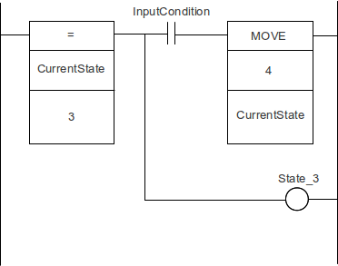
Since
the sequence rungs are almost identical, it is a relatively easy task
to write a spreadsheet macro to automatically generate the sequence
rungs based on a series of state names and descriptions. This
eliminates a lot of tedious programming effort. Single stepping
through the sequence is also very easy as an additional bit can be
placed in front of the move instruction to prevent the sequencer from
changing state until the single step bit is asserted. The
sequencer can also be placed into an arbitrary state by simply
changing the current state value.
Project Development:
Developing a project is done in a top down manner. The steps required to do the process or the sequence are first determined. Then the actuators and sensors required to actually do the process are selected. The PLC is then selected with sufficient I/O capacity. The actuators are assigned to outputs and sensors assigned to inputs. Depending on the amount of operator interaction the HMI size and type is selected.
Unless a project is extremely simple there should always be some sort of HMI. Small graphical HMIs are cheap and will pay for themselves very quickly in reduced downtime by explicitly showing a fault condition saving a lot of troubleshooting time.
The sequence is then written with a high level of abstraction. Rather than placing large amounts of combinatorial code in the sequencer, one or two bits are used which condense the required conditions. For example, a bit labeled “ActuatorsHome” would be used rather than a rung with all the actuator home sensors in series. This makes the program more readable and easier to debug. The combinatorial code to generate the “ActuatorsHome” bit would be placed in another program section.
The output logic would also reside in another program section. Outputs would be conditional on the state bits and other inputs as required for safety, jogging, etc.
Generally a sequence will start with an initialization part which may run only once or every time depending on the automation process. For example at power up the state of a machine may not be known and the tooling may have to be moved individually to guarantee that there will be no crashes. Once the machine is running the initialization phase doesn't need to be run again. Ideally, a machine should require no more than two button presses to start up. The first button press resets the safety circuit and the second button press starts the initialization process.
Dynamic sensor checking is another use of an initialization phase which will repeat every cycle. During one cycle of operation each sensor should be seen to go both on and off. This will verify that no sensor is damaged or misadjusted and is not stuck either on or off. Sensors that should normally be off at the start of the cycle such as part presence sensors would be checked at this time. Cylinder position sensors can be checked by verifying that when the retract stroke sensor is on, the extend stroke sensor is off and vice versa. Off course, any sensor problems would be displayed on the HMI as an error message.
The
next stage of the sequence would be the loading phase where the
program waits for parts to be loaded for an assembly process or for a
set of
input conditions to be met.
The assembly steps then follow and finally the last steps where the completed part is removed and the machine setup to initial conditions to accept the next part.
Once the sequence has been developed, the next step is to identify error conditions and create code to identify the errors and display appropriate messages. Generating code to display error messages can be completely automated, but error condition checking and the error messages themselves are the programmers responsibility. Depending on the HMI, only a few error messages can be displayed at one time, so errors need to be prioritized such that more serious errors are displayed in preference to less serious errors. Priority is assigned by entering high priority errors at the top of the error entry sheet with lower priority errors entered lower down.
To demonstrate project development using the programming tools, an assembly program is developed for a machine which assembles an automotive trim part. The process consists of pressing clips onto a trim piece using pneumatic cylinders.
The sequencer steps are as follows:
0) The safety circuit and air pressure are checked to verify that the machine is able to run
1) The tooling is moved into position to accept the first part and all part presence sensors are off
2) The operator loads the trim piece and clips and then presses a start button to initiate the assembly cycle
3) If all clips and trim piece are present, cylinders are activated to lock the trim piece into place
4) After all locking cylinders are extended, the clip cylinders activate to press the clips into place and the sequencer waits until all cylinders are extended
5) The sequencer then retracts the clip cylinders and waits until they are all retracted
6) The presence of all clips is checked and if any clip is missing, the sequencer jumps to state 8
7) The locking cylinders are retracted, the sequencer waits until the completed part is removed and the sequencer jumps back to state 0
8) The sequencer waits until a key switch is activated to release the bad part
9) The lock cylinders are retracted and the sequencer jumps back to state 0
For safety, a light curtain and e-stop button are present and the incoming air pressure is monitored. If the e-stop button is activated, the light curtain blocked or the air pressure drops, the machine will stop cycling until the start button is pressed. If the sequencer is in state 8 only a key switch can be used to reset the sequencer.
At every step in the sequence the HMI will display what the sequencer is currently waiting on. No cylinder timeouts are used. If a cylinder seizes or a position sensor doesn't turn on, the sequencer will wait until either the sensor goes on or the sequencer is reset by the operator or maintenance person. This makes troubleshooting very easy as the cause for any hangup is immediately apparent. The error code to generate the error message is also very simple. If the valve actuating the cylinder is on, the air pressure is sufficient and the cylinder position sensor is off, then activate the error message. The error message would be something like "Waiting for clip cylinder 1 to extend". Since error messages are prioritized, if air pressure is low or the safety circuit is off, these error messages would be displayed overriding the clip cylinder error message. Once these problems are resolved, the original clip cylinder message would be displayed.
Since automotive quality standards are very high, dynamic sensor checking is used. This means that during the cycle each sensor used for checking part presence should go on and off at least once during the assembly sequence. This makes it impossible for the operator to tape over a misadjusted sensor to get parts through with the risk of a bad part being shipped. During the initialization phase if any sensor is on that should be off, a corresponding error message will be displayed and the sequencer will wait until the sensor is cleared.
Project Management:
PLC Tools was written to automatically generate an easily used sequencer, supply tools to help maintain the symbol table, assign numeric and string variables and also help with HMI programming and bookkeeping tasks.
A spreadsheet is a natural fit with the PLC as it can hold the symbol table, the ladder logic as text based mnemonic code and is also compatible with most HMIs.
The OpenOffice Calc application and OpenOffice Basic macros language are used since they are free, easy to use and work on any operating system. The only weak point is a lack of well organized documentation for Basic programming.
To use PLC Tools, download the file "PLC Worksheet With Embedded Macros.ods". Do not run the file as it will load as read only, save in a convenient location for later loading. The contains a Calc file with the PLC Tools macros and a custom menu command to access the macros through various dialogs.
The default security setting for OpenOffice will prevent the macros embedded in the file from running. Start OpenOffice with a blank Calc file to setup up the macro security settings first.
Click on "Tools" then "Options..." and expand "OpenOffice.org" and then select the "Security" menu item. Then click on "Macro Security..." to bring up the macro security dialog. Select medium security which will ask for confirmation before running any macros. Then click on the "OK" button to complete the security setup and "OK" again to exit the options dialog.
After the macro security has been set, load in the Calc file "PLC Worksheet With Embedded Macros.ods" and click on "Enable Macros". The PLC program development tool macros will now be able to run.
Sequencer Development:
To develop a PLC program we start with the assembly sequence first:
Generating a sequence consists of the following steps:
1) Select a blank Calc worksheet.
1) Click on "PLC Tools..." on the standard toolbar bring up the PLC Tools worksheet select dialog.
2) Click on "Sequencer Worksheet" to create a sequencer worksheet on the current sheet.
3) A sequencer worksheet is a spreadsheet with titles and borders to show the data entry and macro output locations.
4) Under "Sequencer Name" enter the sequencer name and a comment describing the sequence under "Sequencer Comment". These entries will become the variable name and comment for a data memory location holding the current sequencer step number.
5) Under "State Names" and "State Comments" enter the sequence step names and comments for the sequence. These will be transformed into state numbers and state bits used in the sequencer ladder logic. For example, the state name "FirstState" will become the state number "S_FirstState" with value 0 and state bit "B_FirstState" in the symbol table.
6) After all the sequence states have been entered; bring up the sequencer dialog again and click on "Generate Sequencer Code" to generate symbol table entries and mnemonic code.
7) If no symbol table sheet exists, a new sheet labelled "Symbol Table" will be created with entries for the sequencer name, sequencer states and state bit assignments.
A sample Calc file showing the various steps can be downloaded here: Sample Worksheet.
The first sheet, "Sequence entries" shows the state names and comments entered into the worksheet. Only the first three columns contain information as the remaining column data is automatically generated.
The second sheet, "Generated sequence", shows the worksheet after the "Generate Sequencer Code" button in the sequencer dialog has been clicked. The "State # Assignments" and "State Bit Assignments" are for information purposes only. The "Sequencer Mnemonic Code" column contains the ladder code in mnemonic form and the "Output Mnemonic Code" contains a simple code sample for state based outputs.
At this time, the mnemonic code cannot be placed into the PLC as the variables it uses have not been placed into the PLC symbol table. The next step is to work with the symbol table.
Symbol Table Tools:
When the sequencer code is generated, the Calc file is checked to see if a sheet named "Symbol Table" exists. If the sheet doesn't exist, a new sheet is created. The automatically generated variables are then placed into the symbol table sheet. For this example a symbol table worksheet was created first and hardwired I/O assignments were placed into it along with a programmed bit "EnableOutputs".
To create the symbol table worksheet, select a blank sheet and then click on “PLC Tools...” on the toolbar. This will bring up the worksheet type select menu. Click on “Symbol Table Worksheet”. This will create a formatted worksheet named "Symbol Table" which will be used for all subsequent operations. Only the sheet named "Symbol Table" will be used by PLC Tools; renaming the sheet will prevent it from being modified if required.
The sheet named "Symbol table before code generation" shows the symbol table with the manually entered bit assignments.
The following sheet, "Symbol table after code generation" shows the symbol names and types automatically generated by the sequence generation macro. Note that no physical addresses are assigned, this is left to the programmer.
Once a starting address is given, the remaining addresses can be automatically assigned by selecting the symbol names and then clicking on the "Increment Selected Addresses" button in the symbol table tools dialog. A new dialog is spawned asking how bit addresses are to be incremented and then the bit and word addresses in the selection are incremented based on the symbol type. For example an UINT will cause a increment of 1 for the next address, a BOOL will cause an increment of 0.01, an ULINT will increment by 4, etc.
Although Omron supports pointers, there is no mechanism to determine the address of a symbol for use in pointer arithmetic or assignments. Since symbols have static address assignments it is possible to create a new constant whose value is the hex address of a another symbol.
For example the data memory address D100 with symbol name "TableStart" has the hex address #64. A new symbol, A_TableStart of type "NUMBER" could be assigned the value #64 for use in accessing "TableStart" using a pointer. To access TableStart indirectly, the programmer just moves A_TableStart into the indirect address pointer. A problem occurs if TableStart is given a new address and the associated symbol A_TableStart is not changed causing a very nasty and difficult to find bug.
The macro used for incrementing symbol table addresses circumvents this problem by searching the symbol table for symbols prefixed by "A_" and then updates their assigned values to reflect any changes to the address in their associated symbol. For example if TableStart's address is changed to D150 when address increment is activated, then A_TableStart would automatically be changed to #96. Pointer address association can also be triggered by clicking on "Update Address Pointers" in the symbol table dialog.
The symbol table is split into four sections: "Bit Addresses", "Word Addresses", "Constants" and "Timers And Counters". Within these sections there are the columns used in Omron's PLC symbol table along with an additional column used for HMI databases. With the exception of the Timers And Counters section there is no restriction on the type of symbol stored in any section. All the symbol table tools will work whether a symbol is word or bit based. Timers and counters are unique since they are Boolean symbols but use integer addressing; automatic address assigment will only work for timers and counter symbols entered into the Timers And Counters section.
When a timer is used in a program, instead of putting in a timer number directly, use a named constant (Omron type "NUMBER") with a comment instead. This will show a comment in the program beside the timer. For example, if the timer completion bit of timer 3 is named "DwellTime", then use the named constant "T_DwellTime" with a value of 3 and a comment such as "Press down dwell time". The comment "Press down dwell time" will appear next to the timer instruction in the program instead of "Timer number". Also the PLC Tools address increment macro will recognize the "T_" prefix and keep the timer completion bit number (T003) and named constant (NUMBER 3) the same if the timer bit number is changed.
In the sample Calc file, the sheet named "Symbol table after code generation" shows how the symbol table will look immediately after the sequencer code has been generated. State bits, prefixed with "B_" are placed into the bits section. The word containing the current state number is placed into the word address section with an associated address assignment symbol placed into the constants section. State numbers, prefixed with "S_" containing the state number assignments are also placed into the constants section.
The starting data memory address for the sequencer and starting bit address for the can then be entered and incremented and updated using the appropriate symbol table tools to get the final symbol table as shown in the sheet named "Symbol table with assigned addresses". These symbols would then be copied and pasted directly into the Omron PLC symbol table. Sample symbol table
Duplicate symbol names may not always be caught especially when transferring symbols from the spreadsheet to PLC symbol table. The "Validate Symbol Table Names" tool will search for duplicate names in the symbol table sheet and highlight all duplicate entries.
Whenever a macro generates symbol table entries, entered names are checked for duplication and highlighted in both the symbol table and worksheet.
PLC Sequence Program:
Once the symbols have been assigned in the symbol table, the mnemonic code can be copied into the PLC and the final ladder code created. To copy the mnemonic code into CX programmer, select the cells from the Sequencer Mnemonic Code column and copy onto the clipboard (CTRL + C). Switch to CX programmer and select the section where the code is to be copied and change the view to mnemonics (ALT + M) and then paste the the clipboard contents into the mnemonic editor. Change the view back to ladder to see the sequencer (ALT + D).
The sequencer consists of the same code pattern repeated for every state with the first rung consisting of sequencer initialization and testing code. See Generated sequence for a program listing of the generated sequence.
For every state rung, the data memory holding the current sequence step number is compared to its state number constant. If the current state number and rung state number match then the next state number is moved into the sequencer data memory and the bit corressponding to the current state is set.
As generated, the last sequence state will jump back to the first state.
Since there are no conditions within any of the sequence rungs, the sequencer will loop endlessly. To maintain a state, conditional bits are inserted between the compare and the move instruction. For example, in the machine cycle the first step is to verify that all part sensors are off and the cylinder is home. Rather than putting all these conditions within the rung, two conditions are used; PartSensorsClear and PressHome where PartSensorsClear is derived from ClipPresent and SubstratePresent.
Although it may seem unnecessary to create a new bit when the conditions are so trivial, a more complex application may have many more sensors to contend with and placing all the logic within the sequencer rung makes the program hard to read and understand.
Another code section called "Inputs" is used to hold the conditional code for high level conditions such as PartSensorsClear.
Whenever a new bit or word is defined, it should be placed into the Symbol Table worksheet first, incremented as required and then copied into the PLC symbol table. For simple programs this may seem unnecessarily complex, but as the number of symbols grow, the possibility of having two symbols assigned to the same address approaches certainty. This is especially important when multiword symbols are used. One of the most difficult tasks in PLC programming is maintaining symbol table integrity. As much as possible, automated tools should be used to eliminate human error.
For the next rung, conditional bits called AllPartsPresent and Start would be used where AllPartsPresent is derived from ClipPresent and SubstratePresent.
State 2, S_WaitForPressDown, would have bit PressDown as the conditional bit and state 3, S_WaitForPressUp would have bit PressUp as its condition for advancement.
The new program listing is then Sequencer with input conditions and Input conditions. The sequence steps and conditions are very clear and when displayed in monitor mode, the state bit of the currently active state will be highlighted and the state number will be shown as value for ClipInsertion.
PLC Output Coding:
The PLC outputs are conditional on both the current sequencer state and the state of various input sensors, safety conditions, etc. For this example, the cylinder will only be activated if the EnableOutputs signal is active and the the sequencer is in the required state. In addition to the PLC program, there will be a hardwired safety circuit to prevent cylinder operation when the light curtain is blocked or the e-stop activated.
A control power on indicator light is also controlled by the PLC and is lit whenever there is sufficient air pressure and the e-stop safety circuit has been reset.
The EnableOutputs bit is unlatched whenever the light curtain is blocked, the e-stop pressed or the air pressure drops too low. The input section has an additional rung added to control the output enable bit. Revised input conditions
For programmer convenience, an output code sample is automatically generated when the sequence is created. This can be copied and pasted to generate the various output code rungs. The completed output program is shown in the following listing. Output control code. The cylinder valve control is dependent on the sequencer state via the state bit and the output enable bit. The conditions under which the valve will be actuated are self evident.
Error Handling:
The PLC program is now ready to start making parts except for one major problem; when the machine stops there is no obvious way to know why it stopped without hooking up a laptop and checking why the sequencer has stopped.
This is a very expensive way to find out that the air wasn't hooked up properly or the press home sensor is slightly out of position. A small $200 HMI displaying a simple error message such as "Cylinder home sensor off" or "Air pressure low, check air supply" will pay for itself with the first service call.
The problem is that substantially more code is required to generate this kind of error handling and display then is required to actually run the machine! Luckily, the code is easily generated automatically with only minimal HMI programming required. For this example, an EZAutomation EZTouch Jr., 4" mono HMI will be used as it is inexpensive, easy to program and has sufficient display capacity to show four error messages.
A prioritized, vertical scrolling type error message display will be used. With this type of display, the highest priority error is displayed on the first line, the second most prior on the second line and so on for the four error lines. If an error is corrected, then it is replaced by next highest priority error with the remaining error lines updated accordingly.
For the selected HMI this would consist of four lines of "Lookup" text. Each error line has a data memory tag associated with it where the number in the data memory points to a message in the message database in the HMI. For example if the data memory for the first error line contained the value 3, then the third message in the database would be displayed on the first error line. For the four error lines, the PLC only needs to maintain four pointers with each pointer pointing to its required error message inside the HMI message database.
Prioritizing the error messages is done by taking advantage of the normal PLC scan. Low priority errors set pointers to their messages on higher rungs which will be overwritten by higher priority error messages on lower rungs. The very last rung then moves the pointer values remaining after the scan is done into the data memory tags that the HMI reads for its display. These will be the error messages that the operator will see. With every scan, the error messages will be updated. Since only pointers are moved around, the error handler program will run fairly fast.
For HMIs which use the PLC data memory for storing messages, the message pointers will point to the message locations within the PLC message database instead of the HMI message database. The underlying code will remain essentially the same as the error pointers point to either the message number in the HMI or the message inside the PLC data memory. Since the HMI always reads the same location, additional code is generated to copy the PLC message pointed to by the error pointer to the fixed location accessed by the HMI.
The programmer tasks are then to setup an error screen on the HMI with four error lines, define the error messages and error message priorities, generate the error checking code and download the error messages into the HMI database.
The first step is to create an error handler worksheet within the Calc file. Select an unused sheet, start the PLC Tools dialog and click on "HMI Tools..." to bring up the error handler dialog. Change worksheet length so that it is larger than the maximum number or expected error messages. For this application the default size is adquate.
The error message source will be the HMI database which is the default and the selected action will be to create a worksheet. Click on Okay to create an error handler worksheet on the current sheet.
Only two columns need to be filled in; "Error Message" and "Comment". Fill in the error message column starting with the highest priority errro messages first. Whatever is typed here is what will be displayed on the error screen as an error message. Type a descriptive comment in the "Comment" column. This will be very helpful later when generating the error conditions which will cause the error message to be displayed. Simply copying the operator error message is not helpful since the operator doesn't need to know the conditions under which the error will be displayed. The comment should be a message to the programmer indicating the conditions under which to display the error. The "Length" column shows the number or message characters. If the number of characters exceeds the display capability, the background will turn red as a warning sign.
The simplest way to prioritize error messages is to walk through the sequence and see what would cause the machine to stop. Ideally, any condition that would cause the sequencer to stop should have an associated error message.
For this example, the highest priority error message would be that the e-stop button is pressed. The next would be low air pressure, followed by a blocked light curtain and disabled outputs. These would be followed by various state dependent sensor checks. The complete list of error messages for this example is shown in the error message worksheet.
Note that the lowest priority error messages are four blank lines. These are used to clear the error display when no errors are present.
After the error messages and comments have been entered, activate the HMI Tools dialog again and this time select "Generate Code". The dialog will change allowing the number of error lines and the starting message number to be specified. The default four message lines starting with message number one is correct for this application. Click on okay to generate the required symbols and mnemonic code.
The macro will generate the required symbol names and for the error handler but will not assign addresses. These will need to be setup by the programmer preferably by using the symbol table tools to prevent any addressing conflicts or errors.
After the addresses have been assigned, the symbol table can be copied and pasted into the PLC symbol table. Both the word addresses and constants sections have to be copied over. A new section should then be added to PLC code to hold the error handler logic and the mnemonic code copied into it.
The newly generate error handler code is shown in the following listing Error Handler . For every message the P_On condition is used; this needs to be overwritten with the actual conditional error code. The first four error conditions shouldn't be modified as they are required to clear the screen. Subsequent error conditions should be coded as required for the error conditions.
It is not necessary to use elaborate conditions to generate an error message. For example, the home cylinder sensor off error condition is simply that the cylinder home valve solenoid is activated and the home cylinder sensor is off. As long as the cylinder valve is activated and the sensor is off, the message will appear. Under normal operation, the message will appear only while the cylinder is moving back to home. If the sensor is misadjusted, the message will remain on as the cylinder will never activate the sensor giving a clear indication of the problem to both the operator and the service person.
The error is independent of the sequencer state. The cylinder is being told to go up for whatever reason, the valve has been enabled, yet the cylinder doesn't trigger the sensor causing an error message to be displayed. Keeping the error conditions simple reduces the chances of not showing an error and having the machine hang up for an unknown reason causing unnecessary downtime.
The error handler with added conditions is shown in the following listing. Error handler with conditions . The PLC program is now complete and may be downloaded to the PLC. Sample program
HMI Tools:
A very simple HMI program will be used consisting of only one screen displaying four error lines. Each error line will be associated with a data memory tag containing a pointer to a message within the HMI message database.
The first task is to move the data memory tag addresses into the HMI tag database so that the error lines can be programmed on the HMI. The "HMI Tag Manager..." dialog is used to move data between the PLC Tools application and the HMI. The tag names are first exported to an existing CSV type file in the format required by the HMI which is then imported into the HMI tag database.
To create a CSV type file, first create a text file with a descriptive name such as "Tags.txt" in an easily accessible location and then rename the file to "Tags.csv". The file name is not important, only that it can easily be found later when exporting or importing tags or messages.
Browse to the previously defined CSV file and click on okay and then overwrite existing file to export the tag names. On the EZAutomation application click on "Setup", "Import Tags" and "Comma delimited..." to bring up the file browser. Select the CSV file, accept all defaults and messages to import the tag names.
The first error line tag is "HMI_ERRORLINE1" followed by "HMI_ERRORLINE2" for the next lowest priority error message, "HMI_ERRORLINE3" and "HMI_ERRORLINE4".
The error messages must then be exported to a file for importation by the EZAutomation dialog. Select the error handler sheet and select all the error messages in column "B". Call up the File Manager dialog and select "Export Selected Messages To File" to bring up the file manager. Browse to the previously defined "Tags.csv", overwrite and use default message start number of 1.
On the EZAutomation application click on "Setup", "Import Messages" and "Comma delimited..." to bring up the file browser. Browse to "Tags.csv" and accept all defaults and messages to import the messages.
The HMI program can then be downloaded to the screen. HMI program
Although the application is complete, additional screens should be added for jogging and sensor status display as well as a part counter or other features or a truly finished project.
String Handling:
CJ type PLCs have functions for handling null terminated strings. Allocating memory and managing strings is done through the string tools dialog. The two main tools are allocating memory for a single string or allocating memory in the data memory for a table of strings. String tables are used where fixed messages are sent or received by the PLC.
One PLC data word will hold two 8 bit ASCII characters, note that Omron PLCs do not support Unicode. All strings will be terminated with a null character (0x00h) with odd length strings terminated with an additional null character for padding.
Literal hex codes are entered by enclosing them with quotes. Hex code lengths must be multiples of two to match the PLC word length. For example to place the hex code 0xAB into data memory "AB" is placed in the string. Quotation marks are entered as double quotes.
The PLC symbol table doesn't support explicit string allocation therefore strings are broken into the largest allocatable memory units such as ULINT and given unique names and descriptive comments to show that the memory has been allocated.
Each string is also given a fixed pointer name for easy program access.